

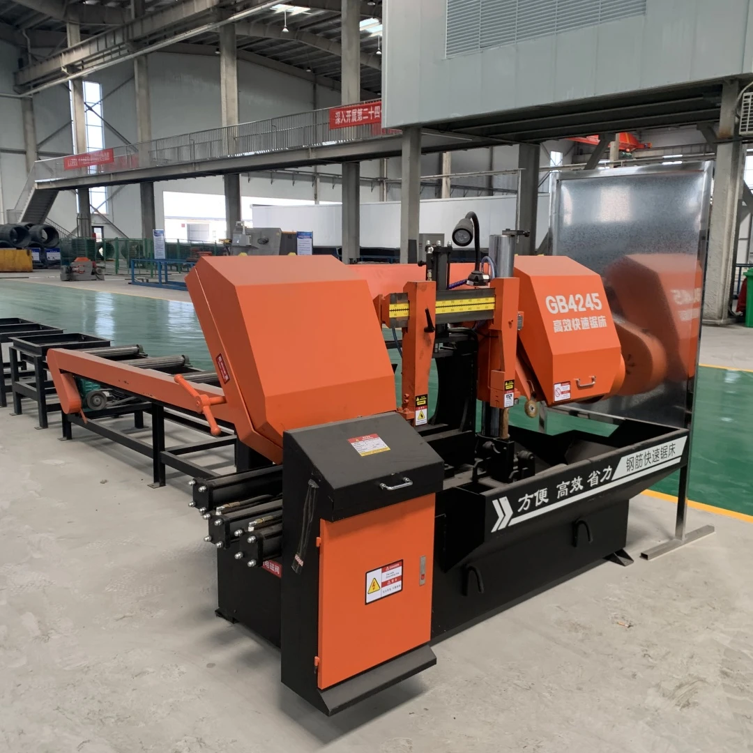
Rebar sawing machines are automated or semi-automated equipment specially designed for cutting metal materials such as rebar and steel pipes. They can precisely cut rebar of different specifications to the set length according to engineering requirements. They are widely used in construction, mechanical manufacturing, steel structure processing, and other fields, and are indispensable cutting equipment in modern rebar processing and industrial production.
- Mechanical transmission system
Feed mechanism: Composed of a servo motor, a ball screw, and a guide rail, the motor drives the lead screw to rotate, which in turn smoothly moves the sawing assembly along the guide rail, achieving precise control of the feed speed. The feed speed range of mainstream equipment is 0–500 mm/min, and the positioning accuracy can reach ±0.1 mm.
Clamping mechanism: It adopts a bidirectional clamping device driven by hydraulic or pneumatic power, equipped with V-shaped clamping blocks, which can firmly clamp steel bars with diameters ranging from 6 to 400 mm, preventing material displacement during the cutting process. The clamping force can be automatically adjusted according to the steel bar specifications, with a maximum clamping force of up to 50 kN.
Support mechanism: It includes multiple adjustable support roller tracks, which are used to support long steel bars to prevent bending deformation caused by the material's own weight. The support spacing can be flexibly adjusted according to the length of the steel bars, meeting the cutting requirements of steel bars up to 12 meters in length.
- Cutting execution system
Sawing assembly: The core components consist of the saw blade and the saw wheel. The saw blade is usually made of alloy material. The diameter of the saw wheel varies by equipment model, commonly 300 mm, 400 mm, or 500 mm. Driven by a motor, the saw wheel rotates at high speed, and the sawing speed can be infinitely adjusted within the range of 20–120 m/min.
Cooling and lubrication system: Integrated with a cooling pump, oil tank, and nozzle, it automatically sprays emulsion or cutting oil during the cutting process. On one hand, it reduces the temperature of the saw blade and extends its service life. On the other hand, it reduces cutting dust and noise while improving the smoothness of the cutting surface.
Core workflow
Parameter setting: The operator inputs the steel bar specifications (diameter, material), cutting length, and quantity through the control system, and the system automatically matches the optimal sawing speed and clamping force parameters.
Material feeding: The steel bars are placed on the support roller conveyor manually or by automatic feeding devices, with one end of the steel bars pressed tightly against the positioning baffle.
Automatic clamping: The clamping mechanism starts, and the hydraulic or pneumatic device drives the clamping blocks to firmly clamp the steel bars, ensuring no loosening.
Sawing processing: The sawing assembly feeds at the preset speed, the saw blade rotates at high speed to cut the steel bars, and the cooling system synchronously sprays cooling lubricating fluid.
After the cutting is completed, the sawing assembly automatically resets, the clamping mechanism releases, and the finished steel bars are conveyed to the designated area by the discharge roller conveyor. The equipment then enters the next processing cycle, and the cutting cycle for a single steel bar can be shortened to 10–30 seconds.